Primary Flight Display: Pilot’s Insight
The primary flight display (PFD) represents one of aviation’s most critical technological innovations, serving as the pilot’s window into the aircraft’s operational status and flight environment. This sophisticated instrument consolidates essential flight data into a single, intuitive visual interface that modern pilots depend on during every phase of flight. Understanding how pilots interpret and utilize the PFD provides fascinating insight into the complexity of aircraft operation and the precision required to safely navigate the skies.
Whether you’re a curious traveler wondering what pilots see in the cockpit or an aviation enthusiast seeking deeper knowledge about flight systems, the primary flight display embodies the marriage of aeronautical engineering and human factors design. This instrument has revolutionized how pilots manage their aircraft, reducing cognitive workload while simultaneously providing unprecedented situational awareness. From takeoff to landing, the PFD guides pilots through every decision point, making it indispensable to modern aviation safety.

What Is a Primary Flight Display?
The primary flight display is the cornerstone of modern cockpit avionics, presenting flight-critical information in a format optimized for rapid comprehension and decision-making. Unlike traditional mechanical instruments scattered across the instrument panel, the PFD consolidates data into one digital screen, typically a high-resolution LCD or LED display. This centralization dramatically improves pilot efficiency, particularly during high-workload phases of flight such as approach and landing procedures.
When exploring aviation topics, it’s helpful to understand that the PFD evolved from decades of cockpit design philosophy. Early aircraft relied on individual instruments—altimeters, airspeed indicators, attitude gyros—that required pilots to scan multiple locations and mentally synthesize the information. The primary flight display revolutionized this process by presenting integrated data in a logical, standardized format. Modern airlines, including those offering flights from Atlanta to Miami, operate aircraft equipped with state-of-the-art PFD systems that represent the pinnacle of this evolution.
The standard PFD layout follows certification requirements established by aviation authorities worldwide, ensuring consistency across different aircraft types and manufacturers. This standardization means that a pilot transitioning between aircraft can quickly acclimate to the new PFD because the fundamental arrangement of information remains consistent. The display typically measures between 8 and 15 inches diagonally, positioned directly in front of the pilot’s line of sight for optimal visibility and minimal head movement required to monitor flight status.
Core Components and Information Display
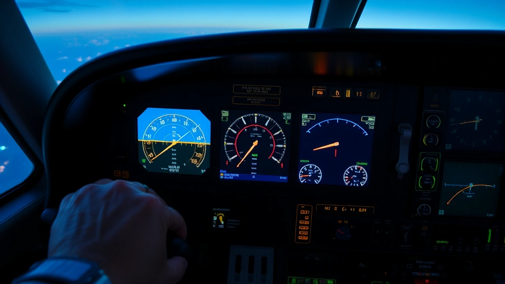
A comprehensive primary flight display presents multiple layers of information simultaneously, yet maintains clarity through intelligent information hierarchy and color coding. The display is divided into logical zones, each dedicated to specific categories of flight data. Understanding these zones helps explain how pilots rapidly assess their aircraft’s status and make informed decisions during flight operations.
The top portion of the PFD typically displays the aircraft’s heading, derived from sophisticated inertial navigation systems and magnetic compass data. The sides present critical performance metrics, while the center focuses on the most important attitude information. This arrangement reflects human factors research demonstrating that pilots naturally focus on the center of their field of view, making central placement of the most critical data a logical design choice.
Color coding plays a vital role in PFD design. Green indicates normal operating ranges, yellow signals caution conditions requiring pilot attention, red indicates emergency conditions demanding immediate action, and white displays reference information or non-normal states. This color language is universal across aviation, allowing pilots to instantly recognize abnormal conditions regardless of their aircraft type. For travelers interested in learning more about aviation operations, our SkyVoyage Hub Blog offers comprehensive insights into modern flight operations.
The PFD also displays various alerts and annunciations, drawing pilot attention to system status changes or procedural reminders. These alerts appear in designated areas of the display, with audio signals accompanying critical messages. The integration of visual and auditory alerts ensures pilots receive important information even if momentarily distracted or during high-workload periods.
Artificial Horizon and Attitude Indicator
The artificial horizon, also called the attitude indicator, occupies the central position on most primary flight displays. This element displays the aircraft’s pitch and bank angles relative to the natural horizon, providing immediate visual feedback about the aircraft’s orientation in three-dimensional space. The artificial horizon is arguably the most important single element of the PFD because it directly communicates the aircraft’s attitude, which fundamentally drives all other flight parameters.
The artificial horizon uses a simple but elegant visual metaphor: a blue sky above a brown earth, bisected by a white line representing the actual horizon. The aircraft symbol, typically a small airplane outline, remains stationary while the horizon moves behind it, creating an intuitive representation of aircraft movement. When the aircraft banks to the right, the horizon rotates left, and the visual feedback matches the pilot’s physical sensations and understanding of aircraft motion.
Modern artificial horizons display additional information overlaid on the basic pitch and bank presentation. Many systems show pitch reference lines, bank angle scales, and flight director commands. Some advanced systems include synthetic vision technology, overlaying three-dimensional terrain representations on the artificial horizon display. This enhancement provides enhanced situational awareness, particularly during approaches to unfamiliar airports or during low-visibility operations.
The artificial horizon’s reliability and accuracy are paramount because pilots depend on it absolutely. Multiple independent sensors feed attitude information to the PFD, with sophisticated voting logic selecting the most reliable source. If disagreement between attitude sources exceeds defined limits, the PFD will alert the pilot to potential instrument failure, preventing reliance on erroneous data.
Airspeed, Altitude, and Vertical Speed
The left side of the primary flight display typically presents airspeed information, displayed on a vertical tape format that many pilots find more intuitive than traditional round-dial airspeed indicators. The airspeed tape displays current airspeed with a thick pointer or tape position indicator, while the background color changes to indicate performance categories. Green represents normal operating speed, yellow indicates caution, and red indicates never-exceed speed ranges.
Airspeed information on the PFD includes multiple reference speeds critical to flight operations. The display typically shows the aircraft’s current airspeed in knots, with reference speeds such as V1 (decision speed), VR (rotation speed), and VREF (reference landing speed) displayed as colored markers. During takeoff and landing, these reference speeds guide pilot actions, helping ensure the aircraft reaches the correct speed at the correct moment.
The right side of the primary flight display presents altitude information in a similar vertical tape format. The altitude display shows current altitude in feet, with a thick pointer indicating the aircraft’s present altitude. The surrounding tape provides context, showing altitude trends and upcoming altitude milestones. Altitude trend information appears as a small tape symbol showing predicted altitude in the next 10-15 seconds, allowing pilots to anticipate altitude changes and adjust pitch control inputs accordingly.
Vertical speed, displayed adjacent to the altitude tape, shows the rate at which the aircraft is climbing or descending in feet per minute. This information helps pilots assess whether current pitch control inputs are producing desired results. When transitioning between flight levels or during approach descents, vertical speed becomes particularly important for maintaining compliance with air traffic control clearances and descent planning.
Understanding these parameters is essential for anyone interested in best airlines for long flights, as modern aircraft with sophisticated PFD systems can execute precise, fuel-efficient flight profiles that older aircraft cannot match.
Navigation and Course Information
The lower portion of the primary flight display presents navigation information, displaying the aircraft’s position relative to planned flight routes and navigational fixes. The navigation display integrates data from multiple sources including GPS, inertial navigation systems, and ground-based navigation aids, providing pilots with precise position information and guidance toward their destination.
The course deviation indicator on the PFD shows whether the aircraft is flying directly toward or away from the selected navigation waypoint or runway. A vertical needle indicates lateral deviation from the intended course, while horizontal deviation information shows vertical alignment with the intended descent path during approaches. This presentation gives pilots immediate visual feedback about navigation performance, enabling precise course tracking.
Modern PFD systems display extensive flight plan information, showing the complete route from departure to destination with all waypoints, airways, and altitude restrictions. Pilots can quickly reference upcoming waypoints, anticipated altitude changes, and route transitions. This integrated approach to navigation reduces the need for pilots to consult separate navigation charts or flight plan documents, keeping attention focused on the primary display.
The distance-to-destination or distance-to-waypoint display helps pilots assess progress toward their goal and calculate fuel requirements. Combined with wind information and fuel burn data, this information enables pilots to make informed decisions about potential alternate airports or fuel management strategies. When planning travel arrangements, understanding that pilots have access to sophisticated navigation tools like those found on flights with multiple passengers helps explain why modern commercial aviation achieves such impressive safety records.
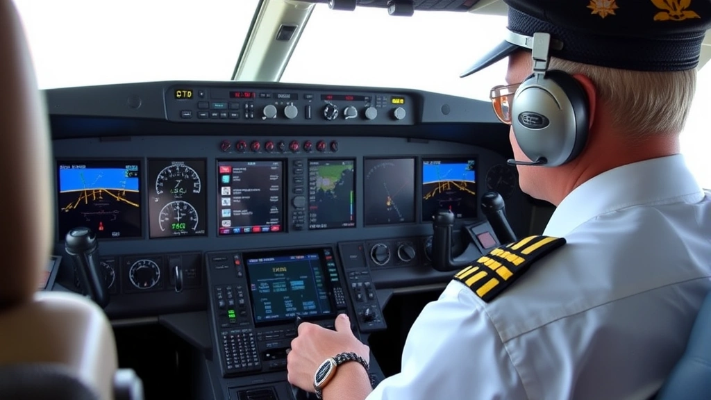
Modern Glass Cockpit Integration
The primary flight display functions as the central hub of modern glass cockpit systems, receiving and processing information from dozens of aircraft sensors and systems. Unlike traditional steam-gauge cockpits where individual instruments operated independently, glass cockpit PFD systems integrate information from autopilot systems, flight management systems, engine monitoring systems, and environmental sensors.
Glass cockpit architecture employs redundant data paths and sophisticated failure detection logic to ensure display reliability. If one sensor fails, the system automatically selects data from backup sensors, often without requiring pilot action. If multiple sensors disagree beyond acceptable tolerances, the PFD alerts the pilot to the discrepancy, preventing reliance on erroneous information. This architecture has contributed significantly to modern aviation’s excellent safety record.
The integration of autopilot information with the primary flight display creates a unified flight management environment. Flight director commands appear on the artificial horizon, showing pilots the pitch and roll inputs required to follow the programmed flight path. Autopilot engagement status, mode transitions, and any autopilot disconnect reasons appear prominently on the display, keeping pilots informed about automation status at all times.
Engine monitoring data also integrates with the PFD in modern systems. While dedicated engine display screens provide detailed engine information, critical engine parameters often appear on the primary flight display, particularly during high-workload phases. Engine failure indications, thrust lever position disagreements, and fuel imbalance warnings all receive prominent display on the PFD, ensuring pilots receive critical information immediately.
Pilot Training and PFD Mastery
Mastering the primary flight display represents a significant portion of modern pilot training. Commercial pilots must demonstrate proficiency with PFD systems during their certification, understanding not only how to interpret information but also how to recognize system failures and respond appropriately. Training syllabi dedicate substantial time to PFD interpretation, starting with basic concepts and progressing to advanced scenarios involving system failures and degraded modes.
Initial pilot training introduces the PFD’s basic layout and information presentation during ground school, with instructors emphasizing the logical organization of information and color coding schemes. Pilots then transition to flight training, first under visual flight rules where they can reference actual horizon and terrain, then progressing to instrument flight rules where they depend entirely on the PFD for orientation and navigation information.
Recurrent training, required annually or biennially depending on pilot certification level, includes PFD system updates and procedural changes. As manufacturers introduce new features or modify display presentations, pilots must remain current with these changes. Simulator training provides a safe environment to practice responding to PFD indications during emergency scenarios, from system failures to unexpected weather encounters.
The transition between different aircraft types requires PFD familiarization training because different manufacturers present information with subtle variations in layout and terminology. A pilot transitioning from one aircraft to another must complete type-rating training that includes detailed instruction on that specific aircraft’s PFD system. This training ensures pilots can rapidly and accurately interpret information regardless of which aircraft they’re operating.
Safety Implications and Reliability
The primary flight display has fundamentally improved aviation safety by reducing pilot workload and improving situational awareness. By consolidating critical information into a single, standardized display, the PFD allows pilots to maintain better overall awareness of aircraft status and flight environment. Research demonstrates that glass cockpit aircraft experience lower accident rates than comparable steam-gauge aircraft, with the PFD contributing significantly to this safety improvement.
Display reliability receives intense scrutiny from aviation authorities worldwide. The Federal Aviation Administration and European Union Aviation Safety Agency establish rigorous certification standards for PFD systems, requiring manufacturers to demonstrate reliability through extensive testing and analysis. Display brightness, contrast, refresh rates, and failure modes all receive detailed specification and validation.
Redundancy represents the cornerstone of PFD reliability strategy. Critical systems like attitude indication employ multiple independent sensors with automatic selection logic, ensuring that single sensor failures don’t degrade display accuracy. Some aircraft employ dual or triple PFD displays, allowing pilots to cross-check information and identify display failures. This redundancy approach has proven highly effective in preventing display failures from causing accidents.
Weather considerations also impact PFD design and operation. Displays must remain readable in bright sunlight while maintaining appropriate brightness during night operations. Modern displays employ ambient light sensors that automatically adjust brightness, maintaining visibility across a wide range of lighting conditions. Glare reduction and anti-reflective coatings further enhance visibility in challenging lighting environments.
Understanding the sophistication of modern flight systems helps explain why airline luggage size restrictions exist—aircraft are engineered to precise specifications, and weight management remains critical to performance and safety. Similarly, when researching the best times to book airline tickets, understanding that modern aircraft operate with exceptional efficiency thanks to advanced systems like the PFD can help explain why ticket prices fluctuate based on demand and fuel costs.
FAQ
What exactly does the primary flight display show?
The primary flight display presents the aircraft’s attitude (pitch and bank), airspeed, altitude, vertical speed, heading, navigation information, and system status. It consolidates the most critical flight information into a single digital display, allowing pilots to assess aircraft status at a glance.
Can pilots fly using only the primary flight display?
Yes, pilots conducting instrument flight rules operations rely entirely on the primary flight display for orientation and navigation. The PFD provides all necessary information for safe aircraft operation in weather conditions where outside visual references are unavailable.
What happens if the primary flight display fails?
Most modern aircraft employ redundant display systems. If one PFD fails, pilots can reference backup displays or revert to standby instruments. Aircraft are certified to operate safely even with certain display failures, though operational limitations may apply.
How often is the primary flight display updated?
Modern PFD systems update information multiple times per second, providing pilots with real-time feedback about aircraft status and environmental conditions. The display refresh rate is typically 30 to 60 hertz, matching the speed at which pilots can process visual information.
Do all commercial aircraft use primary flight displays?
Most modern commercial aircraft employ glass cockpit systems with primary flight displays. Older aircraft may retain traditional steam-gauge instruments, but the aviation industry has largely transitioned to digital display systems due to their superior safety and efficiency benefits.
How do pilots learn to interpret the primary flight display?
Pilot training includes extensive instruction on PFD operation, starting with ground school theory and progressing through simulator training and actual flight operations. Recurrent training ensures pilots remain proficient with PFD systems throughout their careers.